Nevermore PCBs
Controller PCBs for the Nevermore Mini, Nevermore Max, and Nevermore Stealthmax air filters.
Choose your PCB below for mount and wiring instructions, or continue to Firmware & Software Setup.
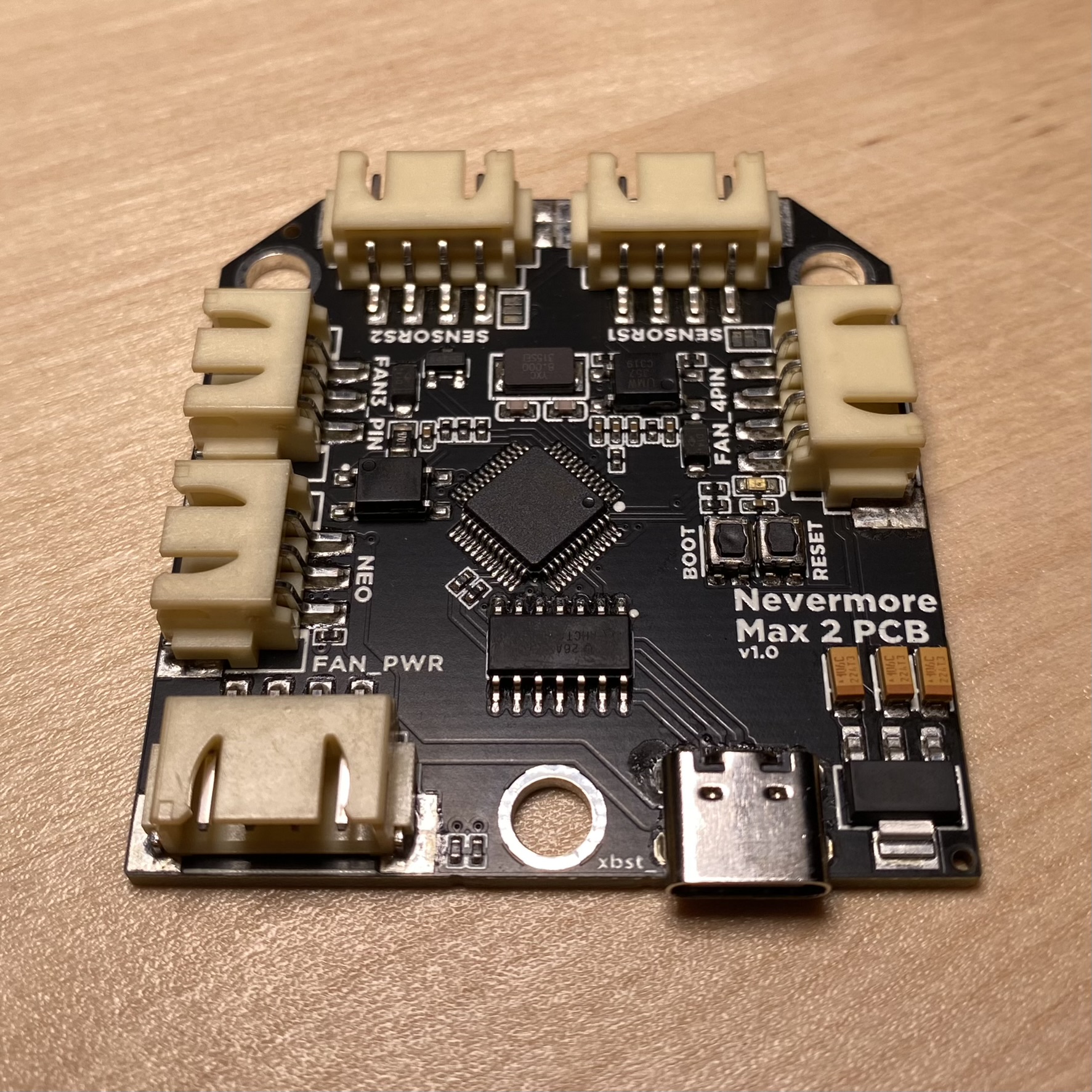
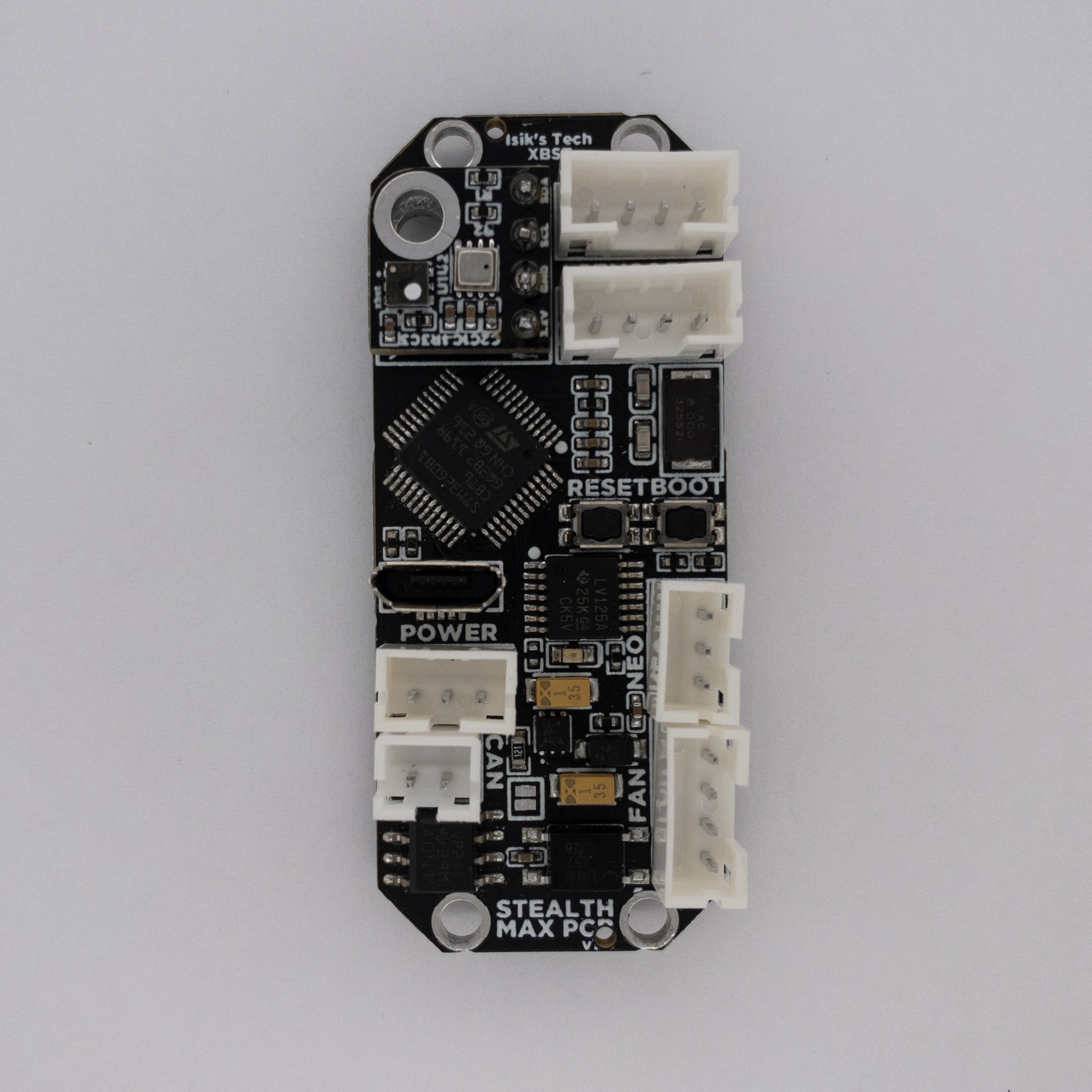
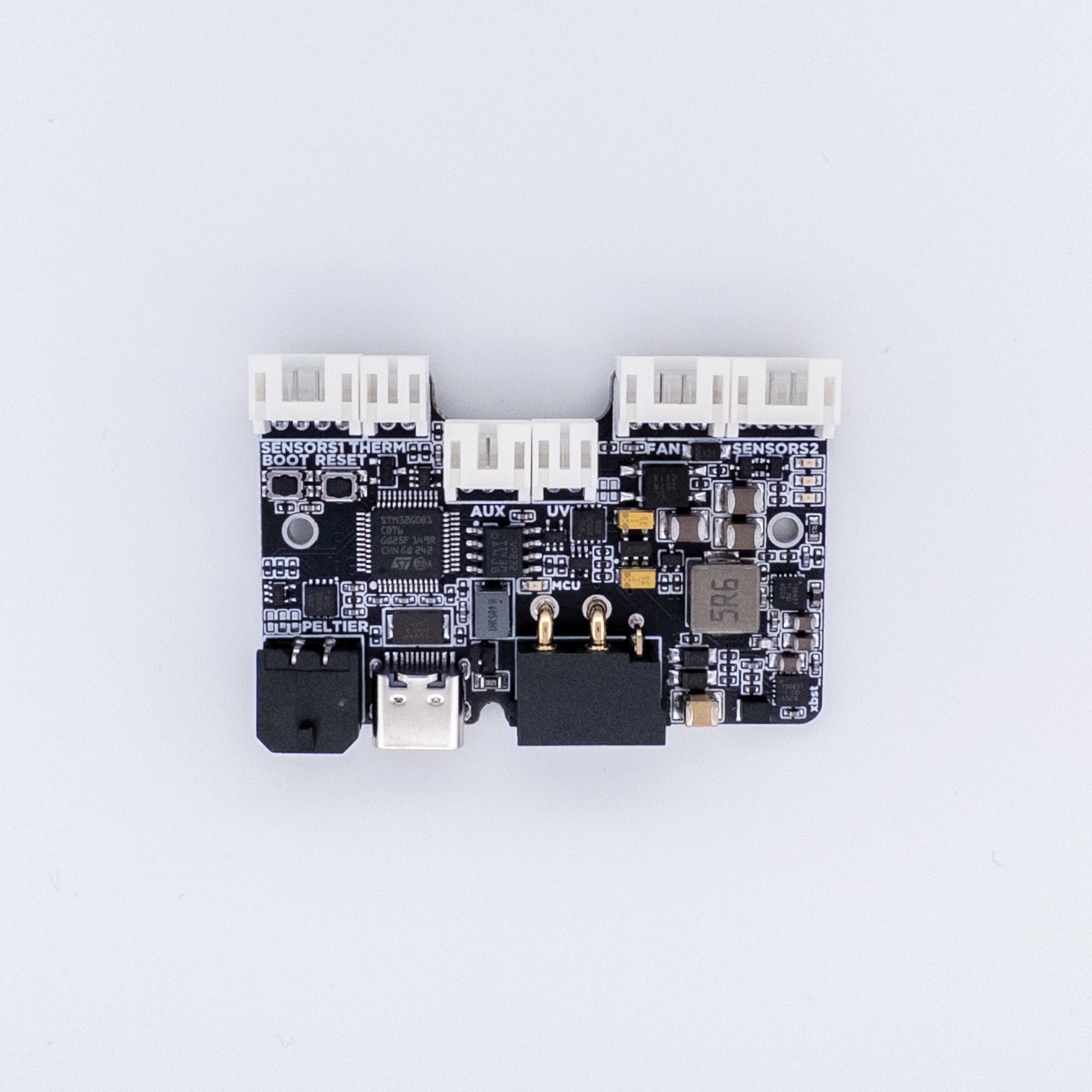
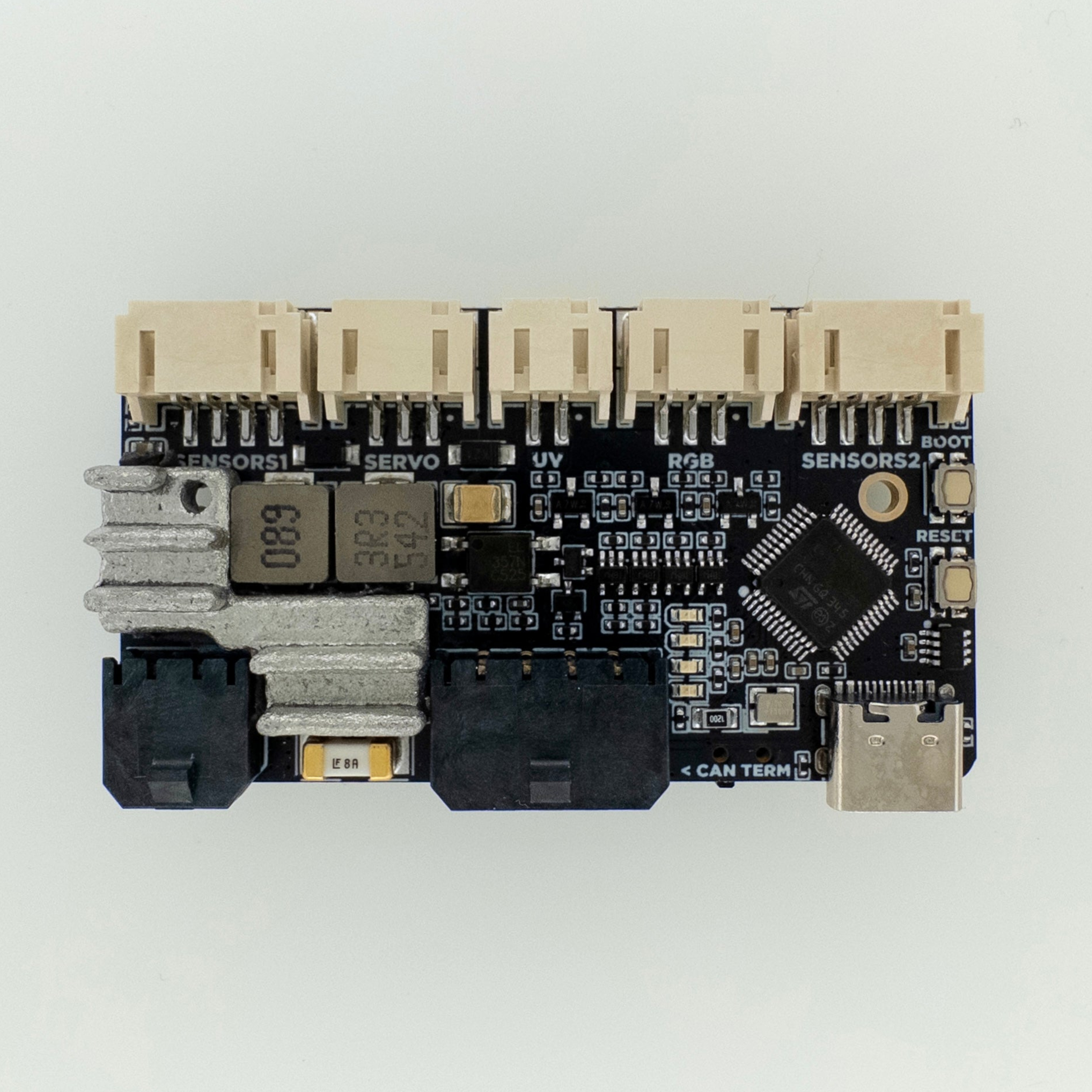
| Click for docs: | Max 2 PCB | Mini & Stealthmax PCB | Stealthmax PCB 2 | Stealthmax PCB 3 |
|---|---|---|---|---|
 |
 |
 |
 |
|
| Nevermore Compatibility | Max 2 | Mini & Stealthmax |
Stealthmax v1 | Stealthmax v2 |
| Fan Control | 1x 4-Pin 1x 3/2-Pin |
1x 4-pin | 1x 4-pin | 1x 4-pin |
| Fan Voltage | Separate 12-24VIN | Separate 12-24VIN | 12V, Needs 24VIN | 24VIN |
| USB Support | Yes | Yes (Vertical USB) | Yes | Yes |
| CAN Bus Support | No | Yes | Yes | Yes |
| ARGB LED Control | Yes | Yes | No | Yes |
| Peltier Control | No | No | Yes | Yes |
| Servo Control | No | No | No | Yes |
| UV LED Control | No | No | Yes (PWM) | Yes (Constant Current) |
| Thermistors | None | None | 1x Port 1x Onboard |
3x Port 1x Onboard |
| Air Sensors | 2x Port | 2x Port Optional Sensor Mount |
2x Port | 2x Port |
| USB Connector | USB C | USB Micro B | USB C | USB C |
| VIN Connector | XH | PH | XT30(2+2) | MX3.0 |
| Internal Connectors | XH | PH | PH (MX3.0 Peltier) | PH (MX3.0 Peltier) |
Resellers
To be updated after Stealthmax PCB 3 release.