Nevermore Stealthmax PCB 2
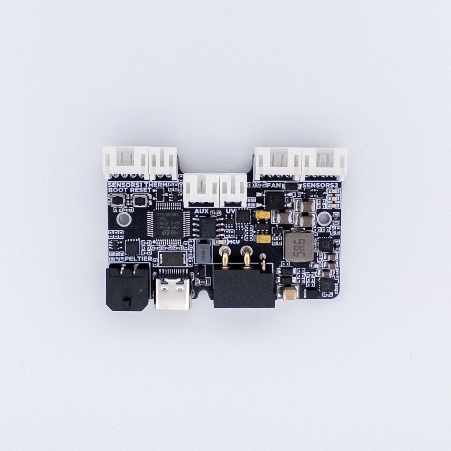
Controller PCB for the Nevermore Stealthmax air filter.
Printed Parts
Download and print the necessary files from the PCB's repo. You'll need to at least print the "Spacer" for your printer size. You can use the stock latch with the Raspberry Pi logo, or download the version from this repo with the Isik's Tech logo.
| Filter | Spacer | Latch |
|---|---|---|
| Stealthmax | Spacer | Latch |
| Stealthmax S | Spacer | Latch |
Mount
- Place the spacer over the screw holes of the electronics chamber of your filter. The top side of the mount (printing orientation) faces down. Align the outer screw holes with the holes on the spacer.
- Attach the heatsink to the PCB, behind the corner with the buck converters. Align its edges with the edges of the PCB. This is where it fits with the spacer:

Wiring
All internal connectors except peltier are JST-PH, peltier is MX3.0. The CAN/VIN connector is XT30(2+2). Use the diagram below to wire your fan, sensors, LEDs, thermistor, and peltier.

Do not hot-plug VIN on your PCB. Always turn your printer off before plugging/unplugging the VIN cable.
Next Steps
Proceed to Firmware & Software Setup for flashing instructions, SGP40 plugin installation, and Klipper config.