Nevermore Stealthmax PCB 3
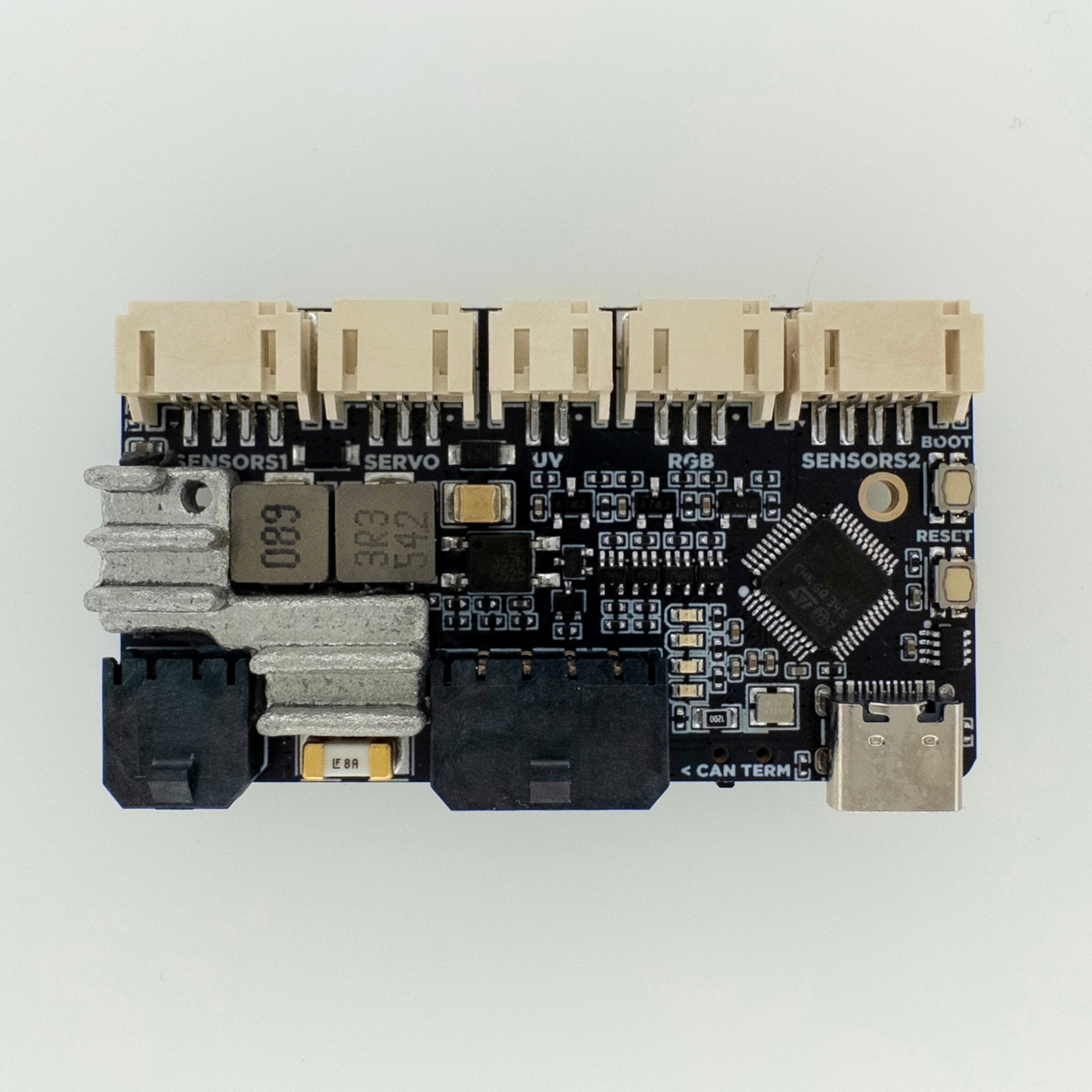
Controller PCB for the Nevermore Stealthmax v2 air filter.
Printed Parts
Below are all the printed parts you can print for your Nevermore Stealthmax PCB 3 setup. You need to print the spacer file, the rest are optional and dependent on your setup.
| Type | Single-Color | Multi-Color |
|---|---|---|
| Spacer (Mount) | Download | N/A |
| Latch | Download | Download |
| XT30(2+2) Port Cover | Download | N/A |
| MX3.0 Port Cover | Download | N/A |
Port Cover (Optional)
- Print and insert the plastic cover into the port.
- Mount the port cover PCB using M3 screws.
- Connect the internal MX3.0 cable to the Stealthmax PCB 3 before mounting it.
Mount
- If using a port cover, mount that first following the above steps.
- Stealthmax PCB 3s ship with the heatsink placed on the board. Make sure this heatsink is on your PCB, and is seated down fully (parallel to the PCB).
- There are 2 mounting screws included with your PCB; one is 10mm long, the other is 8mm. 10mm is used for the heatsink side, and 8mm is used on the other side. Using these screws, mount the PCB in place with the spacer between the Stealthmax and the PCB.

Wiring
All internal connectors except peltier are JST-PH, peltier is MX3.0. The CAN/VIN connector is also MX3.0.
There's a slide switch on the bottom side. Slide it left (toward the "Power & CAN" connector) to terminate the CAN bus (120 Ohm resistor).
Port Cover Pinouts
Micro-Fit CAN Daisy-Chain Port Cover
XT30(2+2) CAN Port Cover
Next Steps
Proceed to Firmware & Software Setup for flashing instructions, SGP40 plugin installation, and Klipper config.